

Excessive fit clearance between a cartridge heater sheath and the mold bore is the leading cause of premature element failure. Standard industry guides frequently mention "tight fit," but fail to quantify how microscopic air gaps increase thermal impedance, trapping heat inside the internal Ni80Cr20 core wire.
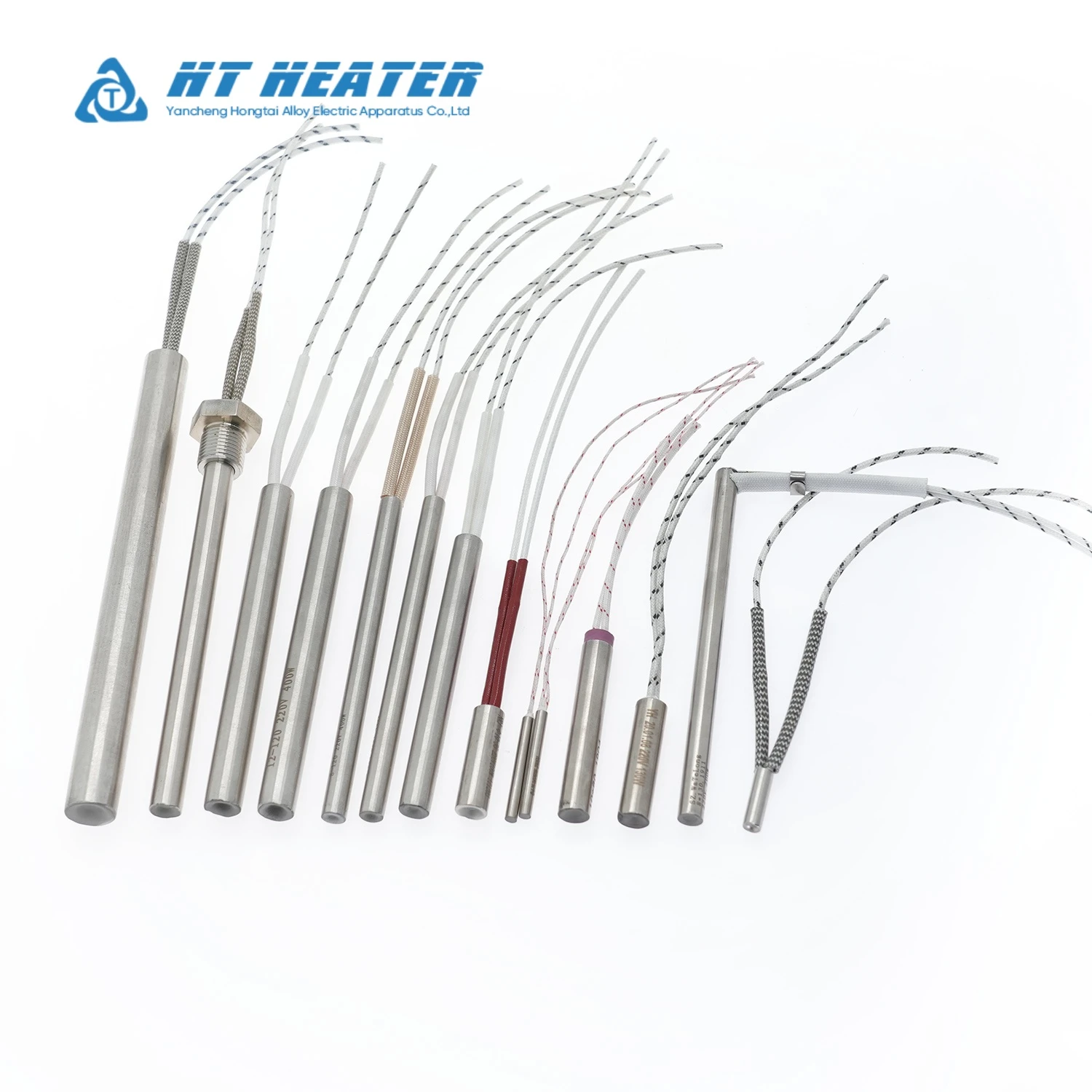
To resolve this, Hongtai Alloy factory manufactures precision centerless-ground Hongtai cartridge heaters. Built with negative outer diameter tolerances, high-purity MgO insulation, and heavy-duty Incoloy 800 sheaths, Hongtai cartridge heaters offer:
Eliminated Thermal Impedance: Precision centerless grinding fits ISO H7 reamed bores to maintain total clearance below 0.08 mm.
Rapid Heat Conduction: Minimizing air gap impedance prevents internal coil burnout under high power densities (up to 30 W/cm²).
Anti-Sticking & Smooth Removal: Controlled thermal expansion prevents sheath distortion, seizing, and bore damage during replacement cycles.
1. The Physics of Air Gap Thermal Impedance & Heater Burnout
Cartridge heaters operate via conductive heat transfer. Heat generated within the internal resistance wire must transfer through compressed Magnesium Oxide (MgO), across the metal sheath, over the air gap, and into the mold metal.
Air Insulation Effect: Air is an exceptional thermal insulator with a thermal conductivity of approximately 0.026 W/(m·K), compared to MgO at ≈ 30 W/(m·K) and tool steel at ≈ 45 W/(m·K).
Heat Trapping Mechanism: A clearance gap as small as 0.2 mm creates a severe thermal barrier. Generated heat cannot escape into the metal tool, causing sheath and core temperatures to spike rapidly.
Coil Oxidation & Failure: Operating internal resistance wires above their temperature limit leads to accelerated wire oxidation, dielectric breakdown, and sudden open-circuit failure.

For a deeper analysis of mechanical compaction, swaging techniques, and thermal dissipation paths in mold heating, engineers can review our specialized technical manual on Precision Swaged Cartridge Heaters: H7 Hole Fit & Heat Transfer Guide.
2. Fit Clearance Formula & ISO Tolerance Standards
Achieving optimal heat transfer requires calculating true Fit Clearance rather than relying on nominal pipe or drill sizes.
2.1 Fit Clearance Calculation
Fit clearance is defined as the difference between the minimum internal diameter of the bored tool hole and the maximum outer diameter of the cartridge heater sheath:
Fit Clearance = Measured Hole Internal Diameter (ID) - Measured Heater Sheath Outer Diameter (OD)
Example: A reamed mold hole measuring 12.02 mm fitted with a cartridge heater sheath measuring 11.95 mm results in a Fit Clearance of 0.07 mm.
2.2 Reamed Hole Tolerances vs. Hongtai Sheath Manufacturing Limits
To guarantee a slide fit without excessive air gap, Hongtai Alloy factory manufactures cartridge heaters with strictly controlled negative tolerances:
| Nominal Heater Diameter | Hongtai Sheath OD Tolerance | Recommended Mold Hole Tolerance (ISO H7) | Max Target Fit Clearance |
| 1/4" (6.35 mm) | 6.28 mm – 6.32 mm (-0.03 mm / -0.07 mm) | 6.35 mm +0.012 mm / 0 mm | 0.08 mm (0.003") |
| 3/8" (9.52 mm) | 9.45 mm – 9.49 mm (-0.03 mm / -0.07 mm) | 9.52 mm +0.015 mm / 0 mm | 0.09 mm (0.0035") |
| 1/2" (12.70 mm) | 12.62 mm – 12.66 mm (-0.04 mm / -0.08 mm) | 12.70 mm +0.018 mm / 0 mm | 0.10 mm (0.004") |
| 5/8" (15.88 mm) | 15.80 mm – 15.84 mm (-0.04 mm / -0.08 mm) | 15.88 mm +0.021 mm / 0 mm | 0.10 mm (0.004") |
| 3/4" (19.05 mm) | 18.96 mm – 19.00 mm (-0.05 mm / -0.09 mm) | 19.05 mm +0.021 mm / 0 mm | 0.11 mm (0.0043") |
3. Allowable Watt Density vs. Fit Clearance & Temperature
As operating temperatures rise or fit clearances widen, the maximum allowable surface watt density must be reduced (derated) to prevent element overheating.
| Mold Operating Temp (°C) | Max Watt Density (Clearance ≤ 0.05 mm) | Max Watt Density (Clearance = 0.15 mm) | Max Watt Density (Clearance ≥ 0.30 mm) |
| 150°C | 30.0 W/cm² (193 W/in²) | 18.0 W/cm² (116 W/in²) | 8.0 W/cm² (51 W/in²) |
| 300°C | 22.0 W/cm² (141 W/in²) | 12.0 W/cm² (77 W/in²) | 5.0 W/cm² (32 W/in²) |
| 450°C | 15.0 W/cm² (96 W/in²) | 7.5 W/cm² (48 W/in²) | 3.0 W/cm² (19 W/in²) |
| 600°C | 8.0 W/cm² (51 W/in²) | 3.5 W/cm² (22 W/in²) | Not Recommended |
For step-by-step mathematical models and watt density safety factors across different mold alloys, check The Engineer's Guide to Calculating Cartridge Heater Watt Density (2026 Edition).
4. Mechanical Drilling Protocols & Removal Sticking Prevention
Improper hole preparation causes premature burnout or locks the heater inside the mold, making removal during maintenance impossible.
Ream, Do Not Just Drill: Standard twist drills leave rough internal ridges, bell-mouthing, and non-circular cross sections that create localized air pockets. Always finish cartridge holes with an ISO H7 reamer.
Avoid Organic Anti-Seize Compounds: Never apply standard copper-based or petroleum-based anti-seize pastes. Organic binders carbonize into a solid thermal insulator at high temperatures, permanently locking the heater in place.
Use High-Temp Non-Conductive Heat Transfer Paste: Apply thin layers of specialized non-carbonizing ceramic or silicone-based thermal paste, or specify Hongtai split-sheath expanding cartridge heaters for worn bores.
Through-Hole Design: Whenever possible, drill through-holes so stuck heaters can be tapped out from the rear end during maintenance.
5. System Integration & Custom Hongtai OEM Capabilities
Hongtai Alloy factory supplies precision Hongtai cartridge heaters customized for high-duty cycle industrial tooling:
Centerless Ground Precision Sheaths: Outer diameter tolerance control up to ±0.01 mm for tight high-precision mold bores.
Integrated J/K Thermocouples: Internal grounded or ungrounded thermocouple junctions built into the disc end or mid-sheath for rapid PID response.
Distributed Wattage Layouts: Customized internal winding densities that deliver extra power to cold outer mold edges.
For specialized industrial tooling applications involving high-vibration flexing or liquid-tight threaded ports, consult Internal Lead Cartridge Heaters: Flex Durability & Crimp-Free Design or Threaded Cartridge Heaters: Tank & Manifold Engineering Guide.
Frequently Asked Questions (FAQ)
Q1: What is the ideal hole tolerance for a high-density cartridge heater?
The recommended mold hole tolerance is ISO H7. Using an ISO H7 reamer paired with a precision negative-tolerance cartridge heater ensures a fit clearance below 0.08 mm, maximizing heat transfer while allowing smooth insertion and removal.
Q2: Why did my cartridge heater expand and stick inside the mold hole?
Heater expansion occurs when internal heat cannot escape due to a loose initial fit or rough drilled hole surfaces. Trapped heat causes the metal sheath to reach plastic deformation temperatures and oxidize, expanding the tube outward until it seizes against the bore wall.
Q3: Can I oversize the hole if I use thermal grease?
No. Thermal grease or conductive paste is only designed to fill microscopic surface roughness, not bridge large fit clearances (> 0.15 mm). Overusing thermal grease in large gaps leads to paste degradation, carbonization, and dielectric failure.
Ready to eliminate thermal impedance and prevent element seizing in your mold tooling?
Hongtai Alloy factory manufactures custom-engineered.Hongtai cartridge heaters built precisely to your bore tolerances and temperature requirements.
[Download Hongtai Cartridge Heater Technical Specification Sheet & CAD Drawings]