

In high-precision thermal processes-such as medical pouch sealing jaws, micro-injection molding inserts, and semiconductor bonding platens-maintaining exact surface temperatures is critical to prevent thermal degradation. Traditional temperature control systems rely on external thermocouples drilled several millimeters away from the heater bore. This spatial separation introduces severe thermal lag, causing wide temperature oscillations and destructive PID overshoot. Built-in thermocouple cartridge heaters solve this bottleneck by embedding an integrated Type K or Type J thermocouple directly inside the heater core. This engineering whitepaper evaluates integrated sensor architecture, details the physics and signal noise trade-offs between Grounded and Ungrounded sensor junctions, and provides closed-loop control strategies for high-speed dynamic tooling.

1. The Physics of Thermal Lag and PID Overshoot
For thermal control engineers, medical device designers, and mold technicians, controlling temperature in compact tooling fails primarily due to spatial displacement between heat generation and heat sensing:
Spatial Phase Lag: Thermal energy takes time to diffuse through metal die walls. When an external sensor detects a temperature drop, the heater core has already been energized at full power, dumping excess heat into the tool.
PID Overshoot & Thermal Stagnation: This phase lag causes the PID controller to over-correct, driving die surface temperatures tens of degrees past setpoint, damaging heat-sensitive medical polymers or causing flash on molded parts.
Micro-Zone Inaccuracy: In tight tooling footprints, there is often no physical space to drill a separate thermocouple receiving hole next to the cartridge bore.
2. Sensor Junction Selection: Grounded vs. Ungrounded Junctions
The core engineering decision when specifying a built-in thermocouple cartridge heater is selecting the physical connection between the thermocouple junction and the stainless steel or Incoloy outer sheath.
2.1 Grounded Junction (Fastest Response)
In a grounded configuration, the thermocouple wires are TIG-welded directly to the inner surface of the end disc or outer sheath, making the junction part of the metallic outer wall.
Thermal Response Time: Extremely fast (< 0.5 seconds). Because there is zero dielectric insulation barrier between the sheath wall and the sensor, heat conducts instantly to the junction.
Best Application: Dynamic, rapid-cycling processes like medical sealing jaws or high-speed labeling heads where micro-second response prevents seal burn-through.
Trade-Off: Electrical isolation is lost. If ground loops or AC high-voltage noise exist on the machine frame, electrical interference can travel back into sensitive digital temperature controllers.
2.2 Ungrounded (Isolated) Junction (Noise Immunity)
In an ungrounded configuration, the thermocouple junction is fully encapsulated within compacted magnesium oxide (MgO) powder, keeping it physically and electrically isolated from the outer sheath.
Electrical Noise Immunity: Provides complete electrical isolation (> 100 MΩ at 500V DC). Prevents stray AC/DC voltage, static charge from plastic film, or VFD motor drive noise from corrupting thermocouple readings.
Thermal Response Time: Slightly slower than grounded units due to the thin MgO insulation layer, though still vastly superior to external thermocouples.
Best Application: Multi-axis CNC automated tooling, systems utilizing solid-state relays (SSRs) or SCR power controllers, and environments with heavy electromagnetic interference (EMI).
3. Sensor Junction Physics & Selection Matrix
| Performance Metric | Grounded Sensor Junction | Ungrounded (Isolated) Sensor Junction |
| Physical Construction | Welded directly to internal sheath tip | Encapsulated in compacted MgO powder |
| Thermal Response Speed | Instantaneous (< 0.5 s) | Fast (1.0 s to 2.0 s) |
| Electrical Isolation | None (Electrically bonded to sheath) | High (> 100 MΩ electrical resistance) |
| EMI / Ground Loop Resistance | Low (Prone to signal noise/jitter) | Exceptional (Completely isolated signal) |
| PID Temperature Stability | Tightest control in low-noise systems | Highly stable in noisy electrical environments |
| Recommended Applications | Medical sealing jaws, rapid packaging | Multi-cavity molds, VFD-driven automation |
4. Thermocouple Placement Options & Calibration
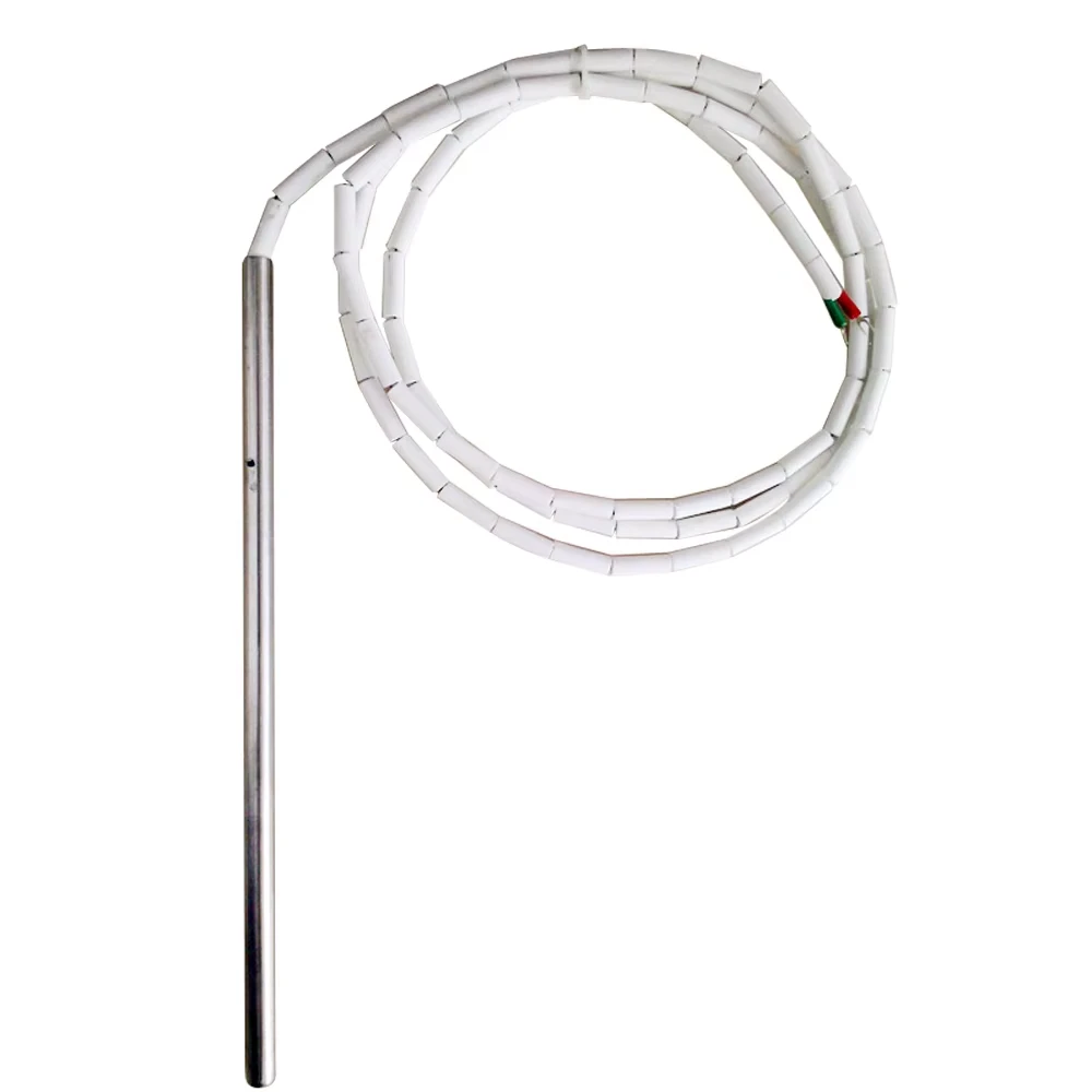
Depending on thermal control requirements, the internal thermocouple junction can be positioned at three strategic locations along the heater length:
Bottom Disc (Tip Sensing): The junction is located directly at the closed end tip. Ideal for monitoring hot runner nozzle tips, blind hole bottoms, or localized seal bars.
Center Body Sensing: The junction is placed at the exact linear midpoint of the active heated length. Ideal for general closed-loop mold plate temperature control and average heat-flux tracking.
Exit Cap Sensing: The junction is located near the lead wire exit header. Used primarily to monitor lead-end temperatures and protect potting seals from thermal degradation.
To ensure accurate signal fidelity across high operating temperatures, review sensor selection principles in Type K vs. Type J Thermocouples: Which is Right for Your Process?.
5. System Integration & Failure Prevention
Match Sensor Calibration to Controller: Standardize on Type K (Chromel-Alumel) for broad temperature range (up to 1100°C) or Type J (Iron-Constantan) for higher sensitivity in lower temperature ranges (below 750°C).
Prevent Lead Wire Strain: Since built-in thermocouple heaters exit with four conductors (two power leads, two TC leads), use high-flex armor or right-angle strain relief headers detailed in L-Shape Cartridge Heaters: 90-Degree Clearance & Strain Relief
Precision Bore Fit: Ensure the cartridge heater is fitted into an ISO H7 reamed hole. Minimal radial air gap optimizes heat conduction away from the sheath tip, preserving thermocouple accuracy as outlined in Precision Swaged Cartridge Heaters: H7 Hole Fit & Heat Transfer Guide
Evaluate Power Densities: Avoid core overheating by properly calculating surface watt loading using The Engineer's Guide to Calculating Cartridge Heater Watt Density (2026 Edition).
If your medical pouch sealer, micro-injection mold insert, or precision semiconductor tooling requires custom built-in thermocouple cartridge heaters, grounded/ungrounded Type K or Type J junctions, or specialized multi-zone layouts, submit your assembly drawings to our thermal engineering team for CAD review and sensor optimization.
[Download Built-In Thermocouple Cartridge Heater Engineering Sizing Guide & CAD Templates ]