

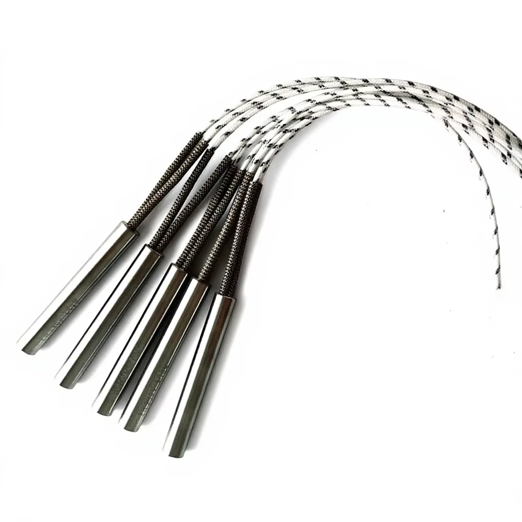
In precision injection molding, die casting, and medical device manufacturing, uniform mold temperature control is directly tied to product quality and cycle times. Precision swaged cartridge heaters are engineered to deliver intense localized heat flux. However, if the thermal impedance at the mold-heater interface is unmanaged, even the most advanced heater cannot deliver its nominal performance.
In high-speed mold manufacturing, premature cartridge heater burnout is a major cause of unscheduled downtime. The vast majority of failures stem from poor thermal conduction across microscopic air gaps between the heater sheath and the mold receiving hole. Trapped heat leads to runaway core temperatures, insulation degradation, and rapid electrical breakdown.
1. Interface Thermal Impedance Physics & Swaging Mechanics
1.1 The Thermal Barrier Effect of Air Gaps
When a cartridge heater operates within a metal mold block, air acts as an exceptionally poor thermal conductor (k ≈ 0.026 W/(m·K), roughly 1/170th that of compacted MgO). Even a microscopic radial air gap acts as an insulating blanket, trapping heat inside the heater core and causing:
Thermal Stagnation & Core Overheating: Heat generated by the NiCr resistance wire cannot dissipate efficiently, causing core temperatures to rise exponentially.
Dielectric Breakdown: Accelerating the dielectric breakdown of the internal magnesium oxide (MgO) insulation layer.
Sheath Oxidation: Trapped air causing localized high-temperature oxidation on stainless steel or Incoloy sheaths, leading to sheath bulging and premature failure.
1.2 Rotary Swaging & MgO Compaction
To eliminate thermal impedance across the sheath-to-bore boundary, high-density swaging processes compress the internal MgO core to near-theoretical crystalline density (> 3.2 g/cm³). This increases the thermal conductivity of MgO from 0.5 W/(m·K) to over 4.5 W/(m·K), dropping the internal resistance wire operating temperature by up to 300°C under equal power loading.
For a comprehensive analysis of MgO crystallization and heat flux sizing principles, see High-Density Cartridge Heaters: Precision Mold Engineering Guide

2. H7 Hole Fit Dynamics & Watt Density Safety
2.1 ISO H7 Fit Standards
In precision mold design, the ISO H7 hole tolerance serves as the gold standard for high-density cartridge heater insertion. Achieving an H7 fit ensures minimal air entrapment around the inserted cartridge heater. Furthermore, as the cartridge heater energizes, the sheath expands faster than the surrounding mold steel, naturally closing the micro-gap during operation.
Operating high-density cartridge heaters in tight-tolerance die holes requires precise heat-flux evaluation to avoid localized burnout. You can calculate safety limits using The Engineer's Guide to Calculating Cartridge Heater Watt Density
2.2 Hole Fit Dynamics vs. Thermal Performance Matrix
| Fit Classification | Bore Tolerance (ISO) | Typical Radial Gap | Thermal Impedance Level | Max Recommended Watt Density |
| Precision H7 Fit | +0.000 / +0.015 mm | < 0.05 mm | Minimal (Optimal conduction) | High (25-35 W/cm²) |
| Standard Reamed | +0.000 / +0.050 mm | 0.05-0.10 mm | Moderate (Requires power derating) | Medium (15-20 W/cm²) |
| Loose Oversized | > +0.100 mm | > 0.15 mm | Severe (High air-gap resistance) | Low (< 10 W/cm²) |
3. System Integration, Micro-Thermal Profiling & Closed-Loop Control
3.1 Micro-Thermal Profiling in Injection Tooling
In multi-cavity injection molds and hot runner manifolds, H7-fitted swaged cartridge heaters are often deployed alongside secondary heating architectures. While cylindrical swaged cartridges deliver localized high-density thermal energy to core inserts, intricate runner systems or nozzles may require specialized helical wrapped heating profiles.
For multi-cavity injection molds requiring specialized micro-zone temperature profiles alongside swaged cartridge heaters, review Hot Runner Coil Heaters: Thermal Profiling & Injection Molding Specs
3.2 Eliminating Thermal Lag & Sensor Matching
Eliminating air gaps drastically reduces thermal lag and accelerates heat transfer rates. Temperature sensors can register die temperature fluctuations almost instantaneously. To capitalize on this fast dynamic response, temperature controllers must be paired with sensors matching the thermal dynamics and operating environment of the mold.
Pair your precision-fit heaters with proper sensing by following Type K vs. Type J Thermocouples: Which is Right for Your Process?.
4. Installation Best Practices & Failure Prevention
To maintain zero thermal impedance throughout production cycles without risking heater seizing inside tight H7 bores, adhere to the following protocols:
Precision Reaming: Use a final H7 spiral-fluted finishing reamer after drilling mold channels to remove taper and internal burrs.
High-Temp Anti-Seize Agents: Apply a micro-thin layer of non-setting, high-temperature anti-seize thermal paste to facilitate heat transfer and ensure smooth extraction during future maintenance.
Extraction Access Design: Design blind mounting holes with knockout pin access channels, or specify threaded extraction end-caps on the heater sheath.
5. Field Failure Modes & Engineering Countermeasures
Dry-Burning Core Wire Burnout: If sheath discoloration/blistering and clean NiCr coil fracture occur, it is typically caused by excessive clearance. The mold hole must be reamed to ISO H7 specifications, or split-sheath expanding heaters should be used for worn bores.
Contamination Flashover at Lead Exit: If insulation at the lead exit is blackened, it is caused by molten plastic or solvents penetrating porous end seals. Specify silicone potting or hermetic ceramic-to-metal glass seals.
Lead Wire Joint Strain Fatigue: If external lead wires break at the crimp pins, it is caused by dynamic mold movement putting tension on the joints. Specify continuous swaged-in internal lead wires equipped with stainless steel armor sleeving.
If your high-precision injection mold die, hot stamping platen, or thermoforming line requires precision ground H7 tolerance swaged cartridge heaters, high-temperature Incoloy metallurgy, or custom watt-density profiling, click below to submit your CAD drawings to our thermal engineering team.
[Download Precision Mold Cartridge Heater Engineering Sizing Guide & CAD Templates]