

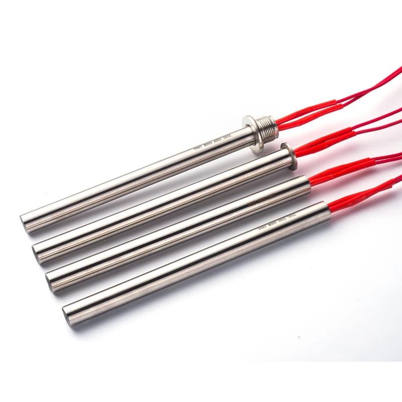
Threaded cartridge heaters (screw plug cartridge heaters) provide compact, high-pressure localized heating for pressurized liquid tanks, oil circulation manifolds, hydraulic reservoirs, and fluid processing lines. However, liquid immersion heating presents severe failure risks if unmanaged: thread interface leakage, localized heater burnout near the mounting boss, and fluid carbonization or scaling. This engineering guide outlines precise thread selection (NPT vs. Metric vs. G/BSP), cold zone (unheated length) rules, and viscosity-driven watt-density limits to maximize service life and eliminate fluid downtime.

1. Primary Failure Modes in Liquid Immersion Heating
For pressurized tank designers, circulation systems engineers, and maintenance supervisors, liquid immersion heating fails primarily due to three core mechanisms:
Thread Interface Leakage under Dynamic Pressure: Thermal cycling causes differential expansion between the hex plug (brass, stainless steel) and the tank boss, weakening sealants and causing fluid weeping or high-pressure leaks.
Thread-Zone Localized Burnout: When the active heating wire extends into the threaded mounting plug or inside the thick tank boss wall, heat cannot dissipate into the fluid. Trapped thermal energy causes rapid localized overheating and resistance wire burnout.
Fluid Scaling and Dry-Burning (Coking): Operating at excessive watt densities burns viscous fluids (oil carbonization) or forms insulating mineral scale (hard water deposits) on the sheath, leading to thermal isolation and eventual element rupture.
2. Thread Specifications & Pressure Sealing Mechanics
Selecting the correct thread profile and sealing method determines the structural integrity and pressure rating of a threaded cartridge heater.
NPT (National Pipe Tapered): Tapered 60-degree threads create a mechanical interference seal along the thread flanks. Requires high-temperature PTFE tape or anaerobic thread sealants. Ideal for North American industrial hydraulic manifolds and pressure vessels.
G / BSPP (Parallel Pipe Thread): Straight threads that do not seal on the thread flanks. Sealing relies on an elastomeric O-ring, bonded washer, or soft copper gasket compressed against the external flat sealing shoulder. Preferred in European equipment and high-maintenance fluid tanks requiring quick replacement.
Metric Threads (e.g., M16x1.5, M20x1.5): Straight threads widely used in compact manifolds and OEM block heaters. Utilizes a flat shoulder washer or fluororubber O-ring seal for tight space constraints.
Thread Selection & Pressure Matrix
| Thread Standard | Thread Profile | Primary Sealing Method | Max Recommended Pressure | Best Application |
| NPT (1/8" to 1") | Tapered 1:16 | Thread flank interference + Sealant | Up to 150 bar (2170 psi) | Hydraulic blocks, high-pressure oil loops |
| G / BSPP (G1/4" to G1") | Parallel (Straight) | Shoulder gasket / O-ring compression | Up to 50 bar (725 psi) | Water tanks, coolant loops, quick-swap modules |
| Metric (M12 to M27) | Parallel (Straight) | Copper washer or sealing flange | Up to 80 bar (1160 psi) | OEM compact manifolds, medical fluid heaters |
3. Cold Zone (Unheated Length) Optimization
To prevent localized burnout near the mounting boundary, a dedicated unheated section (Cold Zone) must extend past the threaded plug and the internal wall of the mounting boss.
The minimum cold zone length (Lcold) must satisfy:
Lcold = Thread Plug Height + Boss Wall Thickness + 15 mm (Safety Margin)
Consequence of Insufficient Cold Zone: Heat generated inside the threaded plug is trapped within steel walls without fluid convection. Sheath temperatures rapidly spike above 600°C, leading to insulation degradation and short circuits right at the hex header.
Fluid Level Fluctuation Allowance: For vertical top-entry mountings, the cold zone must extend at least 50 mm below the absolute minimum liquid line to prevent catastrophic dry-burning in air.
4. Fluid Watt-Density Sizing & Viscosity Derating
Unlike solid metal heating where heat conducts rapidly into an H7 mold bore, liquid heating relies on natural or forced fluid convection. Excessive watt density creates localized fluid boiling, oil coking, or rapid scaling.
To review basic heat flux calculations before derating for fluids, refer to The Engineer's Guide to Calculating Cartridge Heater Watt Density (2026 Edition).
Clean Water / Demineralized Water: High thermal conductivity and convection rates allow higher heat flux.
Recommended Watt Density: 6.0 to 10.0 W/cm²
Hard Water / Water with Additives: Prone to rapid lime-scale accumulation. Lower watt density slows down mineral precipitation on the sheath.
Recommended Watt Density: 4.0 to 6.0 W/cm²
Light Lubricating Oil / Clean Hydraulic Fluid (ISO VG 32-68): Moderate viscosity; requires conservative heat loading to prevent fluid breakdown.
Recommended Watt Density: 2.5 to 3.5 W/cm²
Heavy Fuel Oil / Viscous Thermal Oils: Poor natural convection; high risk of carbon buildup (coking) forming an insulating layer on the heater sheath.
Recommended Watt Density: 1.0 to 2.0 W/cm²
Forced Circulation Glycol / Water Solutions: High velocity forced convection allows increased heat removal.
Recommended Watt Density: 4.5 to 7.0 W/cm²
For larger tank systems or heavy immersion applications requiring flanged mounting plates, compare these parameters with Flange Immersion Heaters: Thermodynamics & Sheath Metallurgy
5. Failure Prevention & Installation Best Practices
Horizontal vs. Vertical Installation: Horizontal mounting is preferred because it establishes natural convection currents along the entire active length. If mounted vertically from the top, ensure the cold zone extends well below the lowest fluid level.
Preventing Galvanic Corrosion: Match sheath metallurgy to tank materials. Use 316L Stainless Steel for water/food processing, Incoloy 800/840 for high-temperature oil/acid solutions, and Brass/304 SS for basic oil reservoirs.
Periodical Scale Inspection: Scale acts as a thermal insulator. A 1 mm layer of limescale increases sheath internal temperature by over 100°C under constant power. Schedule regular inspection cycles to clean or descale sheath surfaces.
Wiring Protection: Use a localized sealing thermal plug setup or liquid-tight terminal enclosures (IP65 / NEMA 4) to protect electrical connections from fluid splashes, condensation, or steam.
If your liquid tank, hydraulic manifold, or fluid circulation system requires custom NPT/Metric threaded cartridge heaters, leak-proof sealing plugs, or specialized watt-density derating, submit your fluid properties and operating pressures to our thermal engineering team for custom CAD design and calculations.
[Download Threaded Cartridge Heater Engineering Sizing Guide & CAD Templates ]