

Mica band heaters are among the most widely deployed heating elements in polymer processing, including injection molding machines, blown film lines, and high-speed twin-screw extruders. Constructing a high-reliability mica band heater involves wrapping a precision-etched nickel-chromium (NiCr 80/20) ribbon around a specialized dielectric mica sheet, which is then encapsulated inside a stainless steel or aluminized steel protective outer sheath.
In high-output extrusion environments, mica band heaters frequently experience premature failure, thermal degradation, and erratic temperature control. These issues stem from dielectric breakdown under high temperatures, localized overheating caused by air gaps between the band and the barrel, and dynamic thermal expansion that loosens clamping bands over time. This engineering whitepaper examines the mineralogical differences between muscovite and phlogopite mica, clamping mechanics, heat transfer physics across barrel interfaces, and field failure prevention protocols.
1. Muscovite vs. Phlogopite Dielectric Mineralogy
Mica is a naturally occurring phyllosilicate mineral characterized by exceptional dielectric strength and high thermal stability. The two primary mineral forms used in industrial band heaters are Muscovite (White Mica) and Phlogopite (Amber Mica).
| Dielectric Property | Muscovite Mica (White Mica) | Phlogopite Mica (Amber Mica) |
| Chemical Composition | KAl2(AlSi3O10)(OH)2 | KMg3(AlSi3O10)(OH)2 |
| Max Continuous Temp | 500°C / 932°F | 800°C / 1472°F |
| Dielectric Strength | 25 - 40 kV/mm | 15 - 25 kV/mm |
| Thermal Conductivity | 0.45 - 0.52 W/(m·K) | 0.35 - 0.42 W/(m·K) |
| Flexibility & Shear Strength | Superior elasticity and punchability | Higher brittleness, lower shear strength |
Muscovite Advantage: Muscovite offers superior mechanical strength and higher dielectric breakdown resistance, making it ideal for standard plastic processing up to 300°C - 350°C barrel operating temperatures.
Phlogopite Advantage: Phlogopite handles significantly higher continuous temperatures (up to 800°C peak), making it essential for high-temperature engineering resins such as PEEK, PEI, and PTFE extrusion.

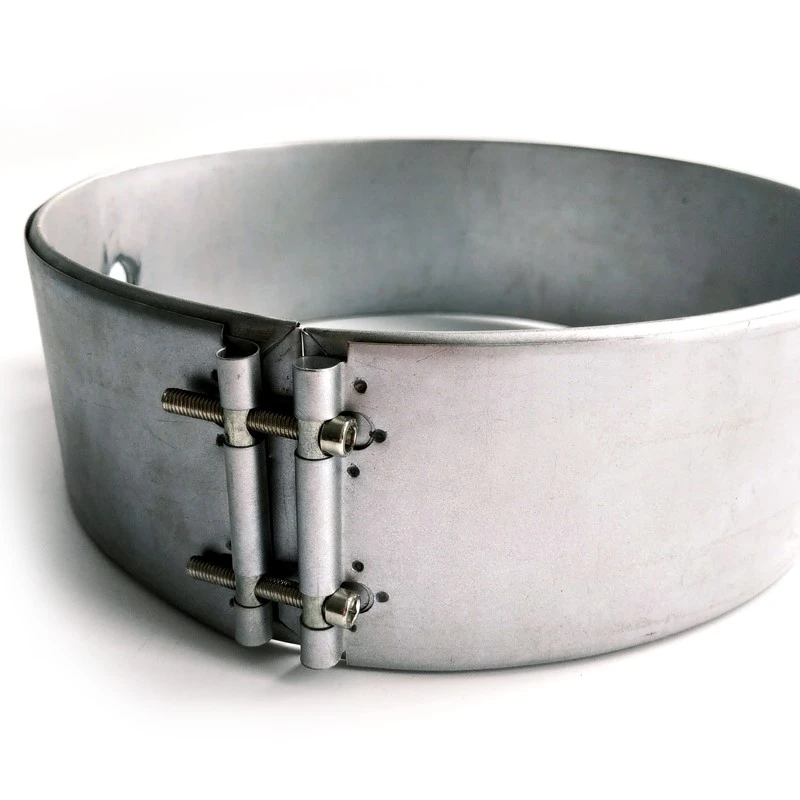
2. Sheath Clamping Dynamics & Thermal Interface Gap Elimination
The primary source of heat transfer resistance in mica band heaters is the interfacial air gap between the inner metallic sheath of the band heater and the outer surface of the extruder barrel.
Thermal contact conductance (hc) across the interface is defined by:
q = hc •(Tband - Tbarrel)
Where h_c depends directly on clamping pressure (Pclamp) and surface roughness (Ra):
hc = C• (Pclamp)m / Ra
Thermal Expansion Mismatch: As the barrel reaches operating temperature, the outer metallic sheath expands faster than the barrel body due to direct contact with the internal resistance ribbon. If clamping straps are loose, an insulating air gap (kair ≈ 0.026 W/(m·K)) develops, trapping heat inside the mica layer and causing localized wire burnout.
Spring-Loaded Clamping Mechanism: Utilizing spring-loaded clamping bolts maintains continuous radial compressive force across thermal expansion and contraction cycles, preserving intimate metal-to-metal contact.
3. High-Speed Extrusion Barrel Thermodynamics & Heat Transfer
High-speed polymer extrusion requires both conductive heat transfer from external heaters and internal shear heat generation from the rotating extruder screw.
Heat Energy Balance:
Qtotal = Qconduction + Qshear - Qlosses
Barrel Heat Flux Limits: Standard mica band heaters operate effectively at surface watt densities between 3.5 W/cm² and 4.5 W/cm² (22 to 30 W/in²). Exceeding 5.0 W/cm² risks rapid dielectric binder degradation and short-circuiting.
4. Custom Watt-Density Profiling & Closed-Loop Control Integration
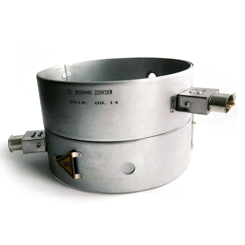
Zoned Thermal Profiling: Modern extrusion barrels are divided into multiple heating zones (Feed, Transition, Metering, Die). Mica band heaters can be manufactured with custom watt-density profiles along their circumference to offset local cooling or heat loss at barrel flanges.
Thermocouple Integration: Precision cutout holes or built-in spring-loaded thermocouple adapters allow direct barrel-surface contact for Type J or Type K thermocouples.
Cross-Reference Sizing Frameworks: Verify maximum allowable surface loading thresholds using surface watt density limits and heat flux calculations. For sensor calibration, consult integrated Type K and Type J thermocouples. For barrel insulation alternative options, cross-reference How to Correctly Install & Clamp Mica Band Heaters to Eliminate Air Gaps.
5. Field Failure Modes & Engineering Best Practices
Plastic Contamination & Carbonization: Molten polymer drool seeping into the open seams of mica bands creates a conductive carbon track across the ribbon element, leading to short circuits. Solution: Specify barrel-sealed mica bands with folded overhanging sheath edges or protective outer cowlings in contamination-prone zones.
Inadequate Initial Retightening: Upon initial startup, thermal expansion and bedding-in of the mica layers cause clamping tension to drop by up to 40%. Solution: Mandate a hot retightening protocol: energize the heater to 150°C, de-energize, and immediately re-torque all clamping bolts to recommended specification (5 - 7 N·m).
If your high-speed polymer extruder, injection molding barrel, or thermoforming line requires custom mica band heater design, high-temperature phlogopite insulation, or spring-loaded clamping mechanisms, click the button below to connect with our senior thermal engineering team.
[Download Mica Band Heater Engineering Sizing Guide & CAD Templates]