

In injection molding and extrusion facilities, mica band heaters are widely favored for their rapid heat response and low initial cost. However, maintenance teams frequently report a frustrating issue: premature heater burnout within weeks-or even days-of installation.
While it is common to suspect a manufacturing defect, forensic analysis reveals that over 80% of mica band heater failures stem from improper installation, specifically the presence of microscopic air gaps between the heater sheath and the machine barrel.
This engineering guide details the thermal mechanics of air gap burnout and provides a step-by-step installation and clamping protocol to maximize the operating lifespan of your mica band heaters.

The Physics of Air Gap Failures: Why Air Kills Mica Heaters
Mica band heaters transfer thermal energy almost exclusively through conduction. For conductive heat transfer to be efficient, 100% flush physical contact with the metal barrel is required.
Air is an exceptionally poor thermal conductor:
Thermal Conductivity of Carbon Steel: ~45–50 W/m·K
Thermal Conductivity of Air: ~0.026 W/m·K
When a mica band heater is installed loosely or misaligned, trapped air pockets act as thermal insulation. Heat generated by the internal Nickel-Chrome resistance wire cannot escape into the barrel.
As a result, the temperature inside the air-gapped region skyrockets within seconds, leading to localized hot-spotting. This excessive temperature breaks down the dielectric strength of the mica insulation layers, causing an electrical arc-through to the stainless steel sheath and immediate element burnout.
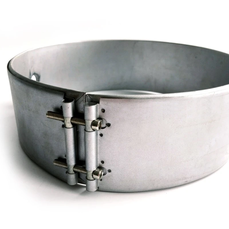
Step-by-Step Installation Protocol to Eliminate Air Gaps
To ensure uniform contact pressure and eliminate air pockets across the entire surface area, follow this standardized installation procedure:
Step 1: Barrel Surface Preparation
Before fitting a new heater, inspect the barrel surface.
Remove Plastic Contamination: Degrease and clean off all plastic resin drool, rust, carbon deposits, and burrs using a wire brush or scraper. Even a 0.1 mm bump of degraded polymer creates a surrounding air gap ring.
Inspect Surface Flatness: Ensure the barrel section is free of deep gouges or warping.
Step 2: Inspection and Pre-Flexing
Carefully open the mica band heater just wide enough to slide over the barrel or nozzle.
Caution: Do not over-flex or bend a mica heater flat. Excessive flexing cracks the rigid internal mica insulation sheets, leading to premature short circuits.
Step 3: Initial Alignment and Clamping
Position the heater over the clean barrel section, ensuring cutouts for thermocouples or melt pressure transducers align cleanly without touching the heater's sheath edge.
Hand-tighten the clamping screws or straps starting from the center of the heater and working outward toward the edges. This center-outward technique pushes trapped air out from beneath the band.
Lightly tap the outer steel sheath of the heater with a rubber mallet around its circumference while tightening. This settles the inner metal sheath flat against the barrel contour.
Step 4: The Critical "Hot Retightening" Cycle (Thermal Expansion Phase)
This is the most routinely skipped step in factory maintenance, yet it is the most critical for eliminating air gaps.
As the barrel heats up to operating temperature, two thermal dynamics occur:
The steel barrel expands outward.
The stainless steel band sheath expands faster than the barrel due to higher surface heat exposure.
This differential thermal expansion causes a newly installed heater to expand away from the barrel, creating fresh air gaps during its first thermal cycle.
The Hot Retightening Procedure:
Turn on the barrel heating zone and raise the temperature to 150°C (300°F).
Allow the heater to dwell at this temperature for 10–15 minutes.
Turn off power to the zone for electrical safety.
Immediately retighten all clamping screws/bolts using insulated hand tools while the heater is hot. You will notice that screws tightened at room temperature can now take 1 to 2 full additional turns.
Bring the barrel up to full process operating temperature (e.g., 250°C–300°C) and perform a final torque check.
Clamping Mechanism Options: Which Style Minimizes Air Gaps?
Selecting the correct clamping hardware for your application significantly reduces maintenance frequency:
| Clamping Style | Mechanism | Best Application | Air Gap Risk |
| Built-in Barrel Straps | Integrated steel straps with socket head screws | Standard nozzle & small barrel bands | Low (when hot-retightened) |
| Separate Clamping Bands | Heavy-duty independent outer clamping band | Large diameter extrusion barrels | Very Low (provides even circumferential pressure) |
| Spring-Loaded Clamps | Heavy compression springs under clamping screw heads | High-cycling continuous production lines | Lowest (springs automatically compress to maintain force during thermal expansion) |
| Quick-Release Latches | Toggle-style mechanical latch | Frequent color changes / nozzle cleaning | Moderate (requires precise adjustment) |
Engineering Tip: For high-temperature or large-diameter applications where manual retightening is difficult, spring-loaded clamping screws are highly recommended. The compression springs absorb thermal expansion differentials, maintaining continuous contact pressure without human intervention.
Common Pitfalls to Avoid
DON'T Use Standard Anti-Seize Paste as a Heat Sink Compounds: Never apply general-purpose copper or graphite anti-seize compounds under a mica band. At temperatures above 200°C, the petroleum binders in these pastes carbonize, forming a conductive carbon track across the mica edges that triggers a short circuit.
DON'T Exceed Maximum Watt Density: Even perfectly clamped mica heaters will fail if driven past their thermal dissipation limit. Ensure your wattage calculations remain below 4.0 W/cm² (25 W/in²). (Calculate your heater safety limits using our Cartridge Heater Watt Density Calculation Guide).
DON'T Ignore Sensor Alignment: If your temperature controller's sensor lags due to poor placement, the PID loop will continuously overdrive the heater. Ensure proper sensor positioning by consulting our Type K vs Type J Thermocouple Selection Guide.
DON'T Over-Torque Cold Screws: Forcing clamping screws beyond recommended torque at room temperature can distort the outer sheath, creating localized raised ripples (which form new air gaps underneath).
Summary Checklist for Shop-Floor Technicians
Before leaving a newly installed mica band heater on a production machine:
1 Barrel surface cleaned, degreased, and burr-free.
2 Heater installed without over-flexing the mica core.
3 Screws tightened from center outward while tapping lightly with a rubber mallet.
4 Hot retightening cycle completed at 150°C.
5 Thermocouple tip securely seated in its pocket without touching heater terminals.
6 Terminal connections insulated and protected against resin leaks.

If your application operates in high-contamination environments where plastic resin leakage is unavoidable, consider upgrading from mica to sealed cast aluminum band heaters or ceramic band heaters. Read our full Industrial Band Heaters Comparison Guide to explore high-durability options.
Need Custom-Fit Industrial Band Heaters?
At HeaterFactory, we engineer custom mica, ceramic, and cast-in band heaters built to tight dimensional tolerances, ensuring exact barrel contact and extended operational life.
[Contact Our Engineering Team for Custom Band Specifications]