

In industrial automation, specifying a high-quality heating element and a precise sensor is only two-thirds of the equation. If the sensor's electrical signal is not perfectly matched to the controller's input architecture, the entire thermal loop will fail.
At Hongtai Heater Factory, our engineers frequently assist OEMs in troubleshooting erratic heating systems. Often, the sensor is mechanically perfect, but a mismatch in temperature controller sensor compatibility-such as wiring a raw thermocouple to a standard PLC analog card expecting a 4-20mA signal-causes massive temperature overshoots or complete system faults.
This guide bridges the gap between thermal hardware and electrical control, detailing the exact step-by-step workflow to match, configure, and troubleshoot temperature sensors for PID controllers and Programmable Logic Controllers (PLCs).

1. Identify the Controller Input: Dedicated vs. Standard Analog
The most common and destructive mistake in thermal automation is confusing a dedicated temperature input module with a standard analog input card.
- Dedicated Temperature Input Modules (Direct Wiring): Many standalone PID controllers and specific PLC expansion cards are designed to directly accept raw signals. They can measure the minute resistance changes of a Pt100 or the micro-volt (mV) signals of a thermocouple. They have built-in reference tables and cold-junction compensation (CJC).
- Standard Analog Inputs (4-20mA / 0-10V): These generic PLC cards cannot read a raw temperature sensor. If your PLC only has standard analog inputs, you must use a temperature transmitter to condition the signal first.
2. Choose the Signal Architecture: Raw vs. Transmitted
Once you know your controller's capabilities, you must decide how to route the signal across your factory.
- Direct Wiring (Raw Signal): Ideal for localized Temperature Control Systems where the sensor is close to the controller. However, long runs of thermocouple extension wire are expensive, and raw Pt100 signals are vulnerable to electromagnetic interference (EMI) from Variable Frequency Drives (VFDs).
- Temperature Transmitters (4-20mA): A head-mounted or DIN-rail transmitter converts the fragile RTD/TC signal into a robust 4-20mA current loop. PlCs heavily favor 4-20mA loops for long factory runs because they are less sensitive to cable voltage drops and are generally more robust against EMI.
3. Matching Sensor Configuration and Controller Software
If using direct wiring, the physical temperature sensor wiring and the controller software parameters must align perfectly.
- The Pt100 PID Controller (RTD Input): A standard Pt100 requires a 3-wire connection to measure and subtract the lead wire resistance. Software Match: Ensure the controller is set to the correct RTD curve. The global industry standard is the IEC 60751 curve (alpha = 0.00385). (Learn more about Pt100 accuracy in our Pt100 temperature sensor guide).

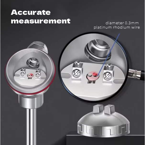
- The Thermocouple Input: The controller software MUST be configured to the exact thermocouple alloy (K, J, N, S, etc.). Cold Junction Compensation (CJC): The controller uses a built-in thermistor to measure the ambient temperature of its terminal block. Do not install the controller where cooling fans blow unevenly across the terminals, as unstable CJC readings will cause the process temperature to drift. (Need help choosing? Review our RTD vs. thermocouple guide).

4. Configuring 4-20mA Transmitters and PLC Scaling
If you are using a temperature transmitter, the PLC must be programmed to interpret the 4-20mA signal correctly based on the transmitter's scaled range.
The Scaling Calculation:
If your transmitter is scaled so that 4mA = 0°C and 20mA = 400°C, the PLC logic uses this linear equation to find the temperature (T) based on the incoming current (I):
T = Tmin + [(I - 4) / 16] x (Tmax - Tmin)
Example: If the PLC reads 12mA, T = 0 + (12 - 4) / 16 x (400 - 0) = 200°C.
If the transmitter range is altered in the field, the PLC software MUST be updated to match, otherwise, the temperature reading will be dangerously incorrect.
5. Control Performance: Thermal Lag vs. PID Tuning
A perfectly matched electrical signal will still cause poor control if the physical thermodynamics are ignored.
If you use a massive, thick-walled protective thermowell, the sensor will suffer from thermal lag. The PID controller will apply full power, but because the sensor is physically slow to detect the heat, the system will severely overshoot the setpoint.
- Engineering Reality: Do not attempt to fix a mechanical hardware issue by aggressively detuning your PID software parameters. Always optimize the probe's diameter and industrial temperature probe design for faster response first, and then run the PID autotune sequence.
6. OEM Integration Checklist for Hongtai
To guarantee seamless integration with your control panels, provide the engineering team at Hongtai Heater Factory with this exact checklist when specifying your PLC temperature sensor:
- Controller Input Type: Direct dedicated temperature input or standard analog (4-20mA)?
- Sensor Type & Standard: e.g., Pt100 (IEC alpha = 0.00385) or Type K Thermocouple.
- Wiring Configuration: 2-wire, 3-wire, or 4-wire (for RTDs).
- Grounding: Grounded or ungrounded thermocouple junction?
- Transmitter Range: If requesting a 4-20mA transmitter, specify the exact temperature scaling (e.g., 0-500°C).
Frequently Asked Questions (FAQ)
Q1: Can I connect one thermocouple to two different PID controllers simultaneously? Generally, no. Wiring a single thermocouple to two parallel controllers will split the micro-voltage signal and introduce ground loops, causing both controllers to display incorrect and erratic temperatures. The most reliable hardware solution is to specify a dual-element thermocouple (two independent sensing junctions built into one physical probe).
Q2: My PLC shows a reading, but it's wildly offset from the actual temperature. Why? If it's an RTD, you likely have an unresolved lead-resistance error (e.g., using a 2-wire sensor on a long run). If it's a thermocouple, you may have configured the controller for a Type J when you actually installed a [Type K thermocouple]. If using a transmitter, verify that the PLC scaling matches the transmitter's programmed temperature range exactly.
Q3: The PID controller displays "OPEN" or "HHHH". What does this mean? This is a standard sensor break alarm. It means the controller detects an open circuit. For a thermocouple, the wire has broken or burned out. For an RTD, one of the excitation wires is severed, or a 4-20mA loop has lost power. Use a multimeter to check the continuity of the sensor leads.
Integrate Your Thermal Control Loop with Hongtai
Specifying the correct Pt100 or thermocouple is only the foundation. Transforming that raw physical temperature into a pristine, EMI-resistant electrical signal-perfectly scaled for your PLC or PID controller-requires deep expertise in both thermodynamics and industrial automation.
Whether you are designing a multi-zone PLC network for a heavy industrial furnace or specifying a standalone PID control panel for an OEM extruder, the engineering team at Hongtai Heater Factory can assist you in selecting the exact signal architectures, wiring configurations, and transmitter ranges required for flawless system stability.
Engineered to exacting standards, Hongtai provides high-fidelity thermal sensors perfectly matched to your automation architecture.
[Contact Hongtai Engineering to Specify Your Sensors for PLC and PID Integration.]