

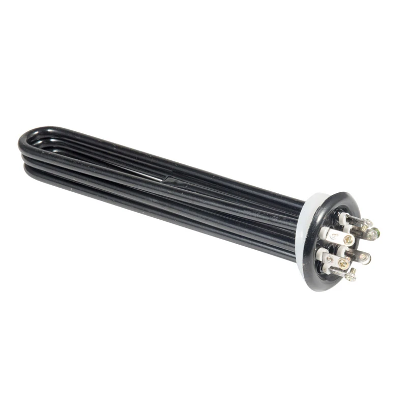
In large industrial storage tanks, chemical reactors, and high-volume circulation loops, flange immersion heaters deliver massive thermal capacities (ranging from 10 kW to over 1 MW). However, design miscalculations in surface watt density, improper flange alloy selection, and poor element spacing cause catastrophic failures-including localized fluid boiling, sheath pitting corrosion, and thermal stratification. This engineering paper evaluates ANSI and DIN flange mounting standards, analyzes the metallurgical degradation mechanisms of 316L stainless steel versus Incoloy 800, and details multi-tube bundle layout geometries that optimize fluid boundary layer heat transfer.
1. Primary Failure Modes in High-Capacity Vessel Heating
For storage tank designers, plant construction engineers, and chemical processing managers, large-scale flange heater failures typically stem from three interrelated thermodynamic and metallurgical breakdown mechanisms:
Boundary Layer Stagnation: Fluid immediately adjacent to the heating element forms a stationary boundary layer. If heat transfer across this thin film is too slow, localized overheating causes film boiling, fluid cracking, or accelerated pitting corrosion on the element sheath.
Metallurgical Chloride & Acid Attack: Standard stainless steels suffer rapid Stress Corrosion Cracking (SCC) and pinhole pitting when exposed to high-temperature chlorides, brackish water, or acidic process solutions.
Thermal Stratification in Large Tanks: Poor element bundle placement creates dead zones where cold fluid settles at the vessel bottom while upper layers overheat, causing uneven thermal expansion and inaccurate process feedback.
2. Metallurgy & Sheath Selection Matrix
Matching flange metallurgy and element sheath material to fluid chemistry prevents galavanic corrosion between the mounting nozzle and element bundle.
| Flange / Sheath Material | Max Temperature | Corrosion Resistance Profile | Typical Tank Applications |
| Forged Carbon Steel Flange / Copper Sheath | 180°C | Low (Clean water only; prone to rust) | Boiler feedwater, fresh potable water tanks |
| 316L Stainless Steel Flange & Sheath | 450°C | Moderate (Resists mild acids & organic compounds) | Food processing, wash tanks, mild chemical solutions |
| Incoloy 800 / 840 Sheath | 750°C | High (Exceptional resistance to oxidation & SCC) | High-temperature air, superheated water, thermal oils |
| Titanium Sheath / 316L Flange | 300°C | Superior (Immune to seawater & chlorine attack) | Seawater desalination, plating tanks, harsh acids |

3. Boundary Layer Heat Transfer & Tube Bundle Geometries
To maximize heat transfer efficiency without exceeding liquid boiling points, elements must be arranged to encourage natural convective buoyancy currents.
Triangular Pitch Layout: Arranging tubular elements in a 60-degree triangular matrix maximizes packing density and induces fluid cross-flow turbulence, shrinking the fluid boundary layer thickness and increasing the convection heat transfer coefficient (h).
Square Pitch Layout: Provides straight, open channels between heating tubes. Essential for viscous or scaling fluids where mechanical cleaning brushes or hydro-jetting must periodically enter the bundle.
Element-to-Element Clearance: Maintain a minimum clearance gap of 1.5 times the tube outer diameter (1.5 × Douter) between adjacent elements to prevent trapped vapor bubbles from forming dry hotspots.
4. Flange Rating Standards & Calculation Sizing
Flange heaters must comply with pressure vessel codes to prevent joint leaks under high operating pressures.
Flange Pressure Standard Selection: Match vessel nozzle specifications using ANSI B16.5 (150 lb, 300 lb, or 600 lb class) in North America or DIN EN 1092-1 (PN10, PN16, PN40) in European and international systems.
Surface Area Calculation: Determine the required total sheath surface area (Atotal) based on allowable fluid watt density (q_watt):
Atotal = Power(KW)/ qwatt
Ensure watt density settings align with fluid limits outlined in Screw Plug Immersion Heaters: Thread Sealing Dynamics, Cold Zone Calculation, and Viscosity Derating Sizing.
5. Mechanical Baffle Supports & Sensor Integration
Internal Baffle Support Plates: Elements longer than 1000 mm require heavy-gauge spacer baffles installed along the bundle length to prevent mechanical sagging and vibration fatigue caused by fluid agitation.
Skin Temperature Thermowells: Weld a dedicated thermowell directly onto the top-most heating element in the bundle. Connect an over-temperature limit controller to shut down power instantly if fluid levels drop.
Watt Density Verification: Validate overall thermal design and power loading using The Engineer's Guide to Calculating Cartridge Heater Watt Density (2026 Edition).
If your chemical storage vessel, circulation heating skid, or industrial fluid processing system requires custom heavy-duty flange immersion heaters, ANSI/DIN flanged elements, or specialized Incoloy/Titanium alloy sheaths, submit your process fluid chemistry and vessel CAD drawings to our thermal engineering team for sizing and metallurgical verification.
[Download Flange Immersion Heater Engineering Sizing Guide & CAD Templates ]