

High-temperature industrial processing-such as advanced ceramics sintering, powder metallurgy, glass refining, and semiconductor wafer annealing-requires operating temperatures that far exceed the physical melting point of standard metallic nickel-chromium or iron-chromium-aluminum heating alloys. Beyond 1200℃, metallic wire elements experience rapid sag, catastrophic creep deformation, and accelerated surface oxidation.
To achieve clean, repeatable thermal profiles at temperatures ranging from 1300℃ to 1800℃, process engineers specify non-metallic Silicon Carbide (SiC) or cermet-based Molybdenum Disilicide (MoSi2) heating elements. However, operating at ultra-high temperatures introduces complex chemical degradation dynamics: SiC elements undergo progressive electrical aging (resistance increase over time), while MoSi2 elements are prone to low-temperature "pest" disintegration (400℃ - 700℃) and mechanical brittleness. This engineering guide addresses material oxidation kinetics, atmosphere control, and dynamic power supply matching.
1. High-Temperature Oxidation Kinetics & Quartz Passivation
Both SiC and MoSi2 rely on the formation of a self-healing protective quartz glass (SiO2) surface layer to resist continuous ambient oxidation.
SiC Passivation Mechanism: At operating temperatures above 1000℃, reaction with oxygen forms a protective silicon dioxide film on the element surface:
2SiC+ 3O2 →2SiO2 + 2CO↑

This passive layer slows down further oxygen diffusion into the recrystallized SiC body. However, as the layer thickens over thousands of operating hours, internal stress causes localized micro-cracking, leading to gradual inner oxidation and increased electrical resistance.
MoSi2 Quartz Glazing Mechanism: Upon exposure to oxygen above 900℃, MoSi2 forms a highly viscous, self-healing layer of pure glass (SiO2):
5MoSi2+ 7O2 →Mo5Si3 + 7SiO2
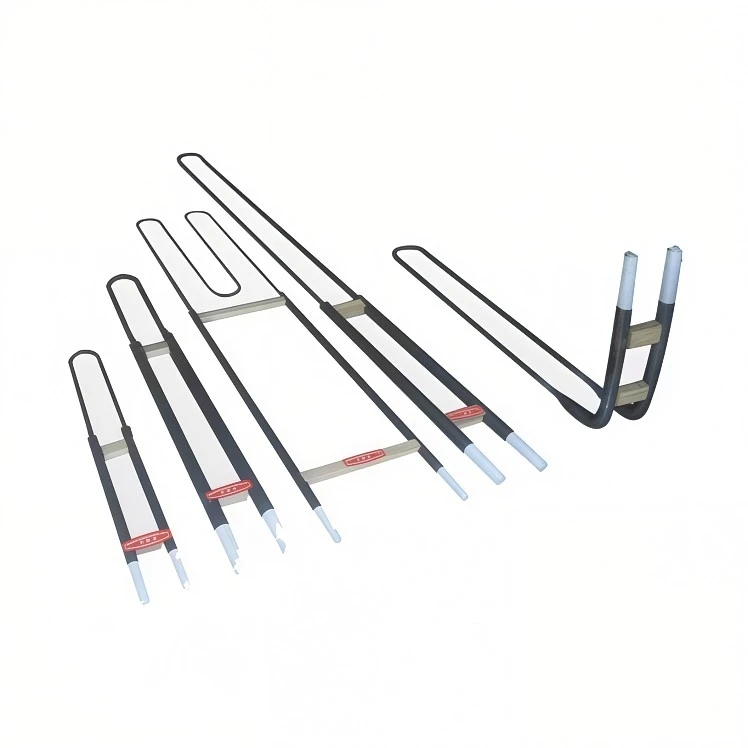
This surface film melts slightly into a glassy glaze that seals microscopic pores. If thermal cycling cracks the coating, fresh substrate reacts with oxygen at high temperature to automatically repair the protective barrier.
2. Electrical Resistivity Curves & Material Aging Characteristics
Understanding the electrical behavior of ultra-high temperature elements is critical for circuit design and transformer selection.
SiC Non-Linear Resistance & Aging: SiC displays a unique negative temperature coefficient of resistance (NTC) from room temperature up to roughly 800℃, above which it transitions to a positive temperature coefficient (PTC). As SiC elements age due to ongoing oxidation, their electrical resistance continuously increases (often increasing by 100% to 300% over their service life).
MoSi2 Non-Aging Characteristics: In contrast to SiC, MoSi2 does not experience electrical aging. Its resistance remains completely constant over years of operation. However, its hot-to-cold resistance ratio is extremely steep (cold resistance is roughly 1/10th to 1/16th of hot resistance), drawing massive inrush current upon cold start if unmanaged.

3. Atmosphere Compatibility Matrix: SiC vs.MoSi2
Furnace atmospheres drastically alter the maximum safe continuous operating temperature of both element types.
| Furnace Atmosphere | SiC Max Temp Limit | MoSi2 Max Temp Limit | Chemical Degradation Mechanism |
| Air / Oxidizing | 1600℃/ 2910°F | 1800℃/ 3270°F | Standard continuous protective SiO2 glass layer formation |
| Pure Hydrogen (H2 Dry) | 1250℃/ 2280°F | 1450℃/ 2640°F | Hydrogen reduces the SiO2 protective layer to gaseous SiO and H2O |
| Nitrogen (N2) | 1400℃/ 2550°F | 1600℃/ 2910°F | Nitridation occurs, forming Si3N4 which alters surface resistivity |
| Vacuum (< 10-2mbar) | 1300℃/ 2370°F | 1500℃/ 2730°F | Silica layer volatilizes due to low ambient vapor pressure |
Process Infrared Cross-Reference: For lower temperature radiant processes (≤ 900℃) like thermoforming or curing where metallic or quartz emitters suffice, engineers should evaluate our whitepaper on The Engineer's Guide to Ceramic Infrared Heaters.
4. SCR Power Control, Current Limiting, and Transformer Tap Matching
Due to the extreme electrical dynamic range of high-temperature elements, direct line-voltage connection will lead to instant fuse blowing or element destruction.
Managing MoSi2 Inrush Current: Because MoSi2 has negligible resistance at room temperature, applying full nominal AC voltage causes massive over-current. Power control panels must feature Silicon Controlled Rectifier (SCR) phase-angle firing equipped with fast-acting current limiting (soft-start ramping).
Managing SiC Aging via Variable Voltage Transformers: To compensate for the 2× to 3× resistance increase of SiC elements over time, furnaces utilize multi-tap secondary transformers or SCR voltage-stepping to gradually increase output voltage (V) as element resistance (R) rises:
Pconstant = Vadjusted2/Raged
Thermal Calculations: When calculating surface loading for high-temperature furnace zones, engineers must cross-reference our foundational rules on surface watt density limits and heat flux calculations
Control Sensors: High-temperature feedback requires specialized thermocouples (Type R, S, or B platinum-rhodium junctions). For a comparative breakdown of lower-temperature sensor pairs, see integrated Type K and Type J thermocouples . For heavy fluid preheating upstream of furnaces, review Flange Immersion Heaters – Fluid Thermodynamics
5. Field Failure Modes & Engineering Best Practices
MoSi2 Pest Oxidation Disintegration : When MoSi2 is held in the range of 400℃ - 700℃ in oxygen, molybdenum reacts to form volatile MoO3 gas, causing the element to crumble into a yellow powder within hours. Solution: Rapidly ramp furnace power through the 400℃ - 700℃critical window during heating cycles.
Cold End Overheating & Wall Insulation Sealing : High-temperature elements feature lower-resistance "cold ends" that pass through the refractory brick insulation. If the passage is not packed with high-purity ceramic fiber wool, hot furnace gases will bypass into the terminal straps, melting aluminum connections. Solution: Maintain positive seal pressure and specify flexible braided aluminum or silver-plated copper straps to accommodate thermal expansion.
If your high-temperature industrial furnace, sintering kiln, or semiconductor annealing system requires custom SiC/MoSi2 element geometry, SCR power control panel design, or refractory mounting support, click the button below to connect with our senior thermal engineering team.
[Download SiC & MoSi2 Furnace Element Engineering Sizing Guide & CAD Templates]