

When sizing a flexible silicone heater, defining the physical footprint and operating voltage is only the baseline. The core of the thermal design is balancing the required heat load with an appropriate watt density.
A frequent design oversight is specifying a silicone heater power calculation based solely on desired heat-up time, without evaluating the substrate's ability to conduct that heat away from the element. When the generated heat flux exceeds the dissipation rate of the mounting interface, the internal element temperature rises until the silicone matrix degrades or the adhesive fails. Application data from Hongtai Heater Factory indicates that a primary cause of early element degradation is localized heat accumulation driven by mismatched watt density and contact resistance.
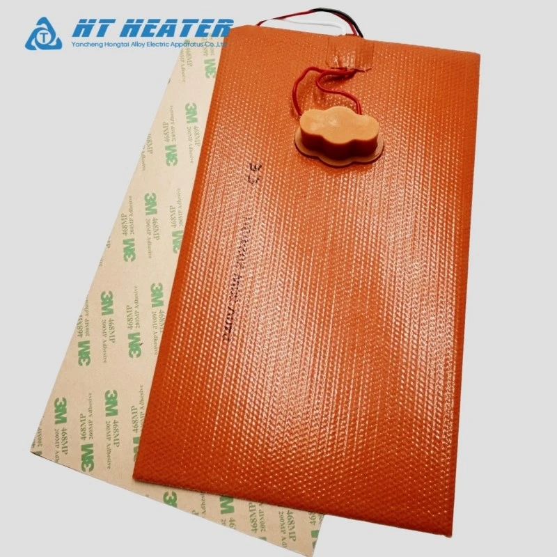
1. Defining Watt Density & A Practical Sizing Example
Watt density (WD) represents the electrical power output per unit of active heating area:
WD = P / A
(Where P = Total Wattage, A = Active Heated Area)
Calculation Example:
Consider an application requiring a 750 W heater with an active surface area of 1000 cm².
WD = 750 W / 1000 cm² = 0.75 W/cm² (4.84 W/in²)
Is 0.75 W/cm² an acceptable watt density?
The number alone cannot answer this. If this heater is vulcanized to a liquid-cooled aluminum block, 0.75 W/cm² is a conservative, highly reliable design. However, if the same heater is attached to a thin steel tank using standard pressure-sensitive adhesive (PSA) and covered in thick insulation, 0.75 W/cm² may cause the adhesive to exceed its thermal limit during a continuous operation cycle. The acceptability of the watt density is dictated by the thermal resistance of the interface.
2. Power Calculation: Heat Load & Steady-State Losses
Before evaluating density limits, the baseline heater power requirement (P total) must be calculated. This consists of the transient power required to reach the setpoint (P heat-up) and the power needed to maintain it against environmental losses (P heat-loss).
P total = P heat-up + P heat-loss
2.1. Heat-Up Power Calculation:
P heat-up = (m · c · ΔT) / t
(Where m = mass, c = specific heat capacity, ΔT = temperature delta, t = required time)
2.2 Steady-State Heat Loss:
Heat is continuously lost through conduction (mounting standoffs) and convection (airflow across uninsulated surfaces). For uninsulated metal components exposed to forced convection, P heat-loss can become the dominant variable in the equation.
Design Note: Standard practice involves calculating the theoretical P total and applying a 20% to 25% safety factor to account for voltage tolerances and unmodeled convective variations.
3. Thermal Contact Resistance (Rth) & Watt Density Limits
The interface between the silicone heater and the workpiece introduces Thermal Contact Resistance (Rth, contact). Higher thermal resistance means the heater must operate at a higher internal temperature to drive the same amount of heat into the part.
Allowable silicone heater watt density guidelines depend directly on minimizing this resistance:
- Factory Vulcanization (Lowest Rth): Bonding the silicone directly to the metal substrate under heat and pressure eliminates air gaps. This allows for higher design watt densities, often evaluated up to 5.0 - 8.0 W/in² (0.8 - 1.2 W/cm²) on aluminum heat sinks.
- Mechanical Clamping (Moderate Rth): Clamps or springs leave microscopic air voids between the heater and the metal, increasing thermal resistance. Watt density is typically derated depending on clamping pressure and surface flatness.
- PSA Mounting (Adhesive Limit): While convenient, PSA introduces a distinct material layer with its own temperature limits (e.g., standard acrylics vs. high-temp silicones). Designs using PSA silicone heaters generally require lower watt densities to prevent adhesive breakdown, unless paired with strict closed-loop PID control.
4. The Internal Thermal Gradient
When reviewing a calculation note, engineers must differentiate between the setpoint temperature and the element temperature.
To maintain a tool surface at 120°C across a moderate-resistance interface, the internal resistance wire may be operating at 150°C. Pushing the watt density higher reduces heat-up time but steepens this thermal gradient. If the required gradient pushes the internal wire temperature beyond the continuous rating of the silicone insulation (typically around 200°C), the design must be revised by either increasing the heater surface area (lowering WD) or improving the mounting method (lowering Rth).
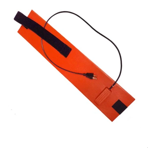
Engineering Support at Hongtai Heater Factory
Translating theoretical heat load calculations into a physical heating element requires evaluating substrate materials, interface methods, and control logic.
Hongtai Heater Factory assists OEM engineers in transitioning from initial thermal calculations to functional heater designs, ensuring the watt density matches the specific boundary conditions of your assembly.
[Contact Hongtai Engineering with Your Custom Heater Watt Density]